First you’ll need to grab the Max232 Adapter from here:
http://www.compsys1.com/workbench/On_top_of_the_Bench/Max233_Adapter/max233_adapter.html#A232DBH
I believe the one I ordered has part number A232DBH3v (I don’t exactly remember as I already had it lying around but, this looks to be the right one.) Just make sure you get the 3.3 volt version of the Max232 adapter. If you are good at electronics, you may want to build your own instead but, this was easiest for me. You’ll also need a USB to DB9 adapter if you want the luxury of doing things over USB from your laptop (which I prefer).
Now on to opening up the router!
Remove the silver piece on each side of the unit. Not sure exactly how I did this since it’s been a couple of years but, it can’t be too hard. I removed them because the unit was overheating and now I do not know where they are so that I can see how they are attached. I’d recommend leaving them off once you get them off.
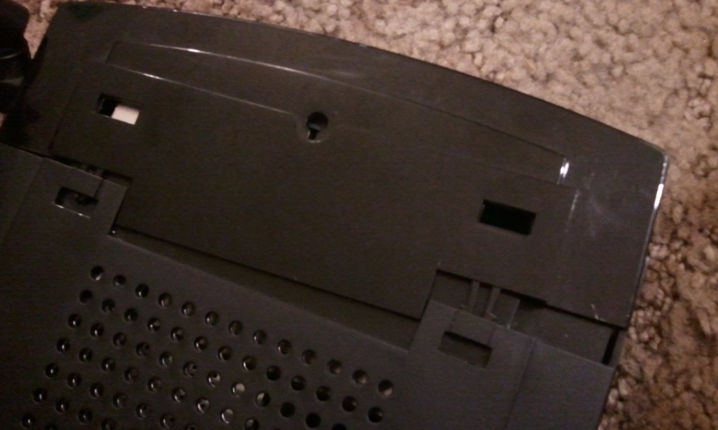
After removing the silver pieces, you need to remove the front display. To do this, simply squeeze together the clips located on the top left and right of the unit and pull outward towards the front of the unit to release the display:
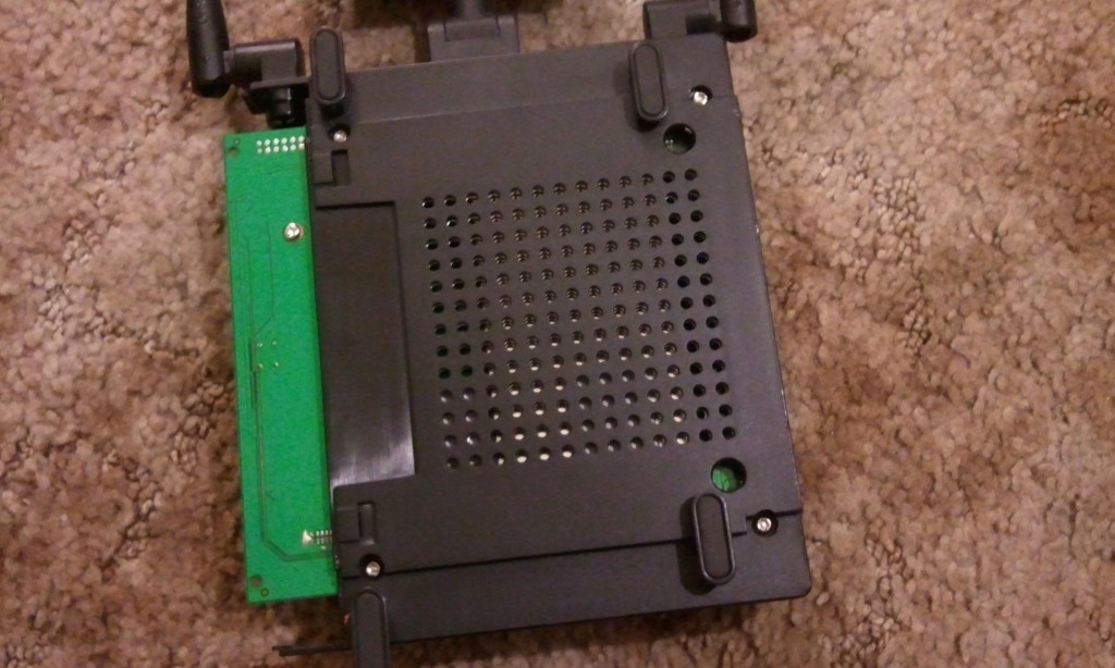
After you have removed the display, remove the light paths by pulling them outward also. They are simple to remove and just snap out of place. Once removed, flip the unit on it’s back and locate 4 screws. You may have to pull the feet of the unit upward and then position them out of the way to get to the front two screws:
Unscrew the screws and flip the unit back topside. Remove the cover to expose it’s main board. Carefully free the antennas by pulling upward on the casing of the antennas. Once the antennas are freed, remove the board from it’s casing by lifting the front of the board to a 45 degree angle and gently pulling outward towards the front of the unit.
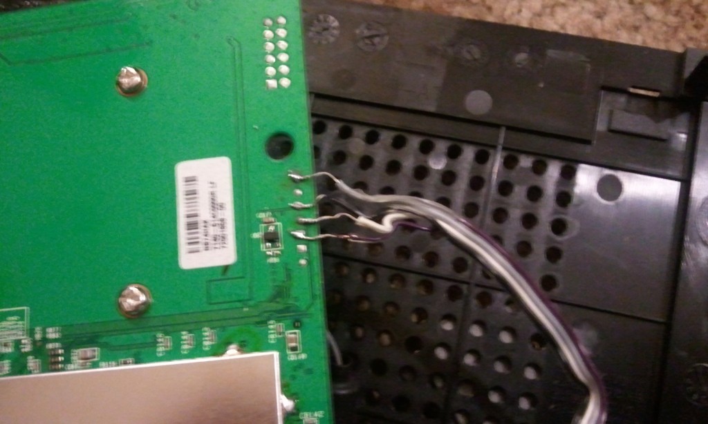
Now that the board has been freed, locate JB3 (it will be labeled and outlined by a box). This is where we will solder our serial cable’s wires. Pin one is the square hole within the JB3 box. This is our VCC or purple wire, as in my pics. Pin two (the round hole to the left of pin one) is our TX, pin three is RX and pin five is ground. Pin four is unused:

Usually you would solder a header onto these points but, I do not have a header and am therefore soldering directly onto the board. You may use a header if you wish.
To make it easier for me, I halve also soldered on the back side of the board:
Remember to keep up with which pin is which if you do the same!
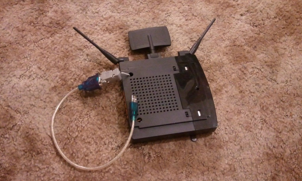
Before soldering, you will need to decide where you want the serial port to come out at. I have threaded mine through a hole on the top back side of the unit but, you may choose wherever you want. You may also require a soldering iron higher than 25W. The solder used by the manufacturer is a high-temp, lead-free solder. Try a 35W soldering iron if you are having problems. I did not have to use a higher watt iron as the solder I had bonded well enough to the existing solder to make a good connection.
Once you have everything soldered, you should test it before putting the unit back together. In short, connect the port to a PC, open telnet, use 115200 for bits per second, 8 for data bits, parity none, 1 for stop bits, flow control none, connect and then boot the device. Telnet should show the boot process.
Now put it all back together:
Congratulations! You have just added a serial port to your Linksys WRT350Nv1 router! You may now pat yourself on the back. ;-)


Comments are closed.